Rendering edges
Table of Contents
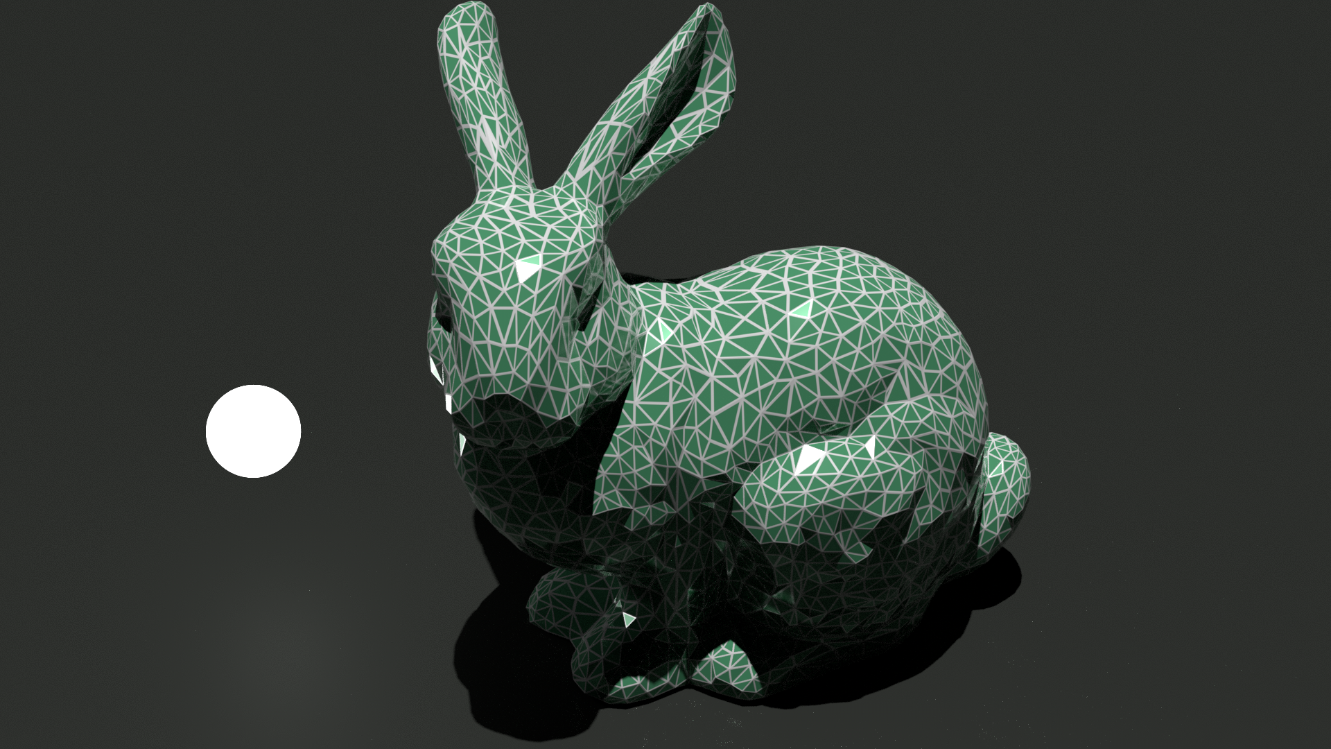
Suppose you want to render the edges of a mesh like in the in the figure:
There are many ways to do this. Here I will use barycentric coordinates. Barycentric coordinates provide a very useful way to represent points relatively to the vertices of a convex polygon, giving us a tool to do all sorts of calculations easily without the need to perform geometric computations.
Barycentric Coordinates⌗
 Given a triangle \(ABC\), with vertices \(A\), \(B\), and \(C\) - and an arbitrary point \(P\).
The barycentric coordinates of \(P\) have three components \(\lambda_i\), each relative to a different
vertex.
This new coordinate system is constructed from the normalized areas \(\triangle\) of the sub-triangles \(ABP\), \(BCP\), and \(PCA\).
Given a triangle \(ABC\), with vertices \(A\), \(B\), and \(C\) - and an arbitrary point \(P\).
The barycentric coordinates of \(P\) have three components \(\lambda_i\), each relative to a different
vertex.
This new coordinate system is constructed from the normalized areas \(\triangle\) of the sub-triangles \(ABP\), \(BCP\), and \(PCA\).

The barycentric coordinates or \(P\) are defined as
$$\lambda_0 = \frac{\triangle ABP}{\triangle ABC}, \quad \lambda_1 = \frac{\triangle BCP}{\triangle ABC}, \quad \lambda_2 = \frac{\triangle PCA}{\triangle ABC}.$$
Notice that, since the areas are normalized by \(\triangle ABC\), we have \(\sum \lambda_i = 1\). This way we can save some computations by using $$\lambda_2 = 1 - \lambda_0 - \lambda_1.$$
Thus, the barycentric coordinates (\(\lambda_0, \lambda_1, \lambda_2\)) represent \(P\). The cartesian coordinates of \(P\) can be retrieved from the relation of each \(\lambda_i\) and their respective vertex position \(A\), \(B\) or \(C\). In other words, \(P\) is the result of a linear combination of the vertices \(A\), \(B\), and \(C\).
$$P = \lambda_0 C + \lambda_1 A + \lambda_2 B$$
Always remember the sub-triangles you form with \(P\). Making \(P\) coincide one of the vertices is the same as having one of those triangles equal \(ABC\) and the other two vanish. You may also realize that each \(\lambda_i\) is associated to an edge \(e_i\) and an opposite vertex \(v_j\). The value of \(\lambda_i\) is the signed distance of \(P\) to the line formed by \(e_i\), and this distance is \(+1\) at \(v_j\). The following figure may help :)

Here are some observations:
- If \(P = A\), then the barycentric coordinates are (\(0,1,0\));
- If \(P = B\), then the barycentric coordinates are (\(0,0,1\));
- If \(P = C\), then the barycentric coordinates are (\(1,0,0\));
- Any point \(P\) inside the triangle will have coordinates \(\lambda_i \geq 0\);
- If \(P\) lies on edge \(AB\), then \(\lambda_0 = 0\);
- If \(P\) lies on edge \(BC\), then \(\lambda_1 = 0\);
- If \(P\) lies on edge \(CA\), then \(\lambda_2 = 0\);
As you may expect now, we will determine how close \(P\) is from any edge using barycentric coordinates! But before that, here is a simple code to compute the barycentric coodinates of \(P\):
// we receive the triangle vertices A, B, and C,
// and we want to compute the coordinates for the given P
hermes::point3 barycentricCoordinates(
				const hermes::point3& A,
				const hermes::point3& B,
				const hermes::point3& C,
				const hermes::point3& P) {
	// the area of a triangle can calculated with the cross product
	// note: we don't need to divide by two here, because when we
	//       divide the areas later the 2's get cancelled out.

	// ABC area using edge vectors AB and CB
	auto ABC_area = hermes::cross(B - A, C - B).length();
	// ABP area using edge vectors AB and BP
	auto ABP_area = hermes::cross(B - A, P - B).length();
	// BCP area using edge vectors BC and CP
	auto BCP_area = hermes::cross(C - B, P - C).length();
	// lambdas are then computed as
	auto lambda_0 = ABP_area / ABC_area;
	auto lambda_1 = BCP_area / ABC_area;
	auto lambda_2 = 1 - lambda_0 - lambda_1;
	return {lambda_0, lambda_1, lambda_2};
}
Detecting Edges in Fragment Shader (GLSL)⌗
The trick now is to determine the barycentric coordinates of our fragment. Because with those coordinates, we can determine if it belongs to an edge or not.
Since we know that the barycentric coordinates of the three vertices of \(ABC\) are $$A = (0,1,0) \quad B = (0,0,1) \quad C = (1,0,0)$$ we can just assign those values as vertex attributes and let the hardware interpolate them throughout the fragments.
Now that we have the barycentric coordinates of our fragment, we need to get the distance to the closest edge. A fragment will be considered an edge if it is closer than the edge width \(W\). In which space the \(W\) is defined is up to the method we use. Perhaps the most naive one is to define \(W\) in the barycentric coordinates space, this way an fragment can be easily classified as edge using
$$\min{\lambda_i} \leq W$$
Depending on the angle of the triangle and the camera view plane, you may also get edges to desapear due to interpolation issues. A way to get around this problem is to weight \(W\) with the total change in barycentric coordinate values on the fragment:
$$\lambda_i \leq (|\frac{dF(\lambda_i)}{dx}| + |\frac{dF(\lambda_i)}{dy}|) * W$$
In GLSL, there is a function called fwidth that computes the sum of the absolute
value of derivatives for a given variable accross fragments. The above test
can be coded in GLSL like this:
in vec3 bc; // fragment barycentric coordinates
uniform float W; // edge width
void main() {
	// compute bc derivatives
	vec3 d = fwidth(bc);
	// here we use a step function perform the check
	vec3 f = step(d * W, bc);
	// check if any lambda is passed the test
	if(min(min(f.x, f.y), f.z) < 1) {
		// edge!
	}
}
Using OSL (Open Shading Language)⌗
Here I’ll take the chance to give an example using OSL. In order to compute the
barycentric coordinates of our point \(P\), we can use some variables that OSL provides for us:
| Variable | Description |
|---|---|
P |
position of the point being shaded |
u and v |
2D parametric coordinates - for the current primitive - of P |
dPdu and dPdv |
Partial derivatives tangent to the surface ate P |
The vertices of our primitive (assuming a triangle here) can then be calculated like this:
A = P - (u * dPdu) - (v * dPdv)
B = A + dPdu
C = A + dPdv
Now, we again have the 3 vertices \(A\), \(B\), and \(C\), and a point \(P\). The rest goes as usual.
Compensating Triangle Shapes⌗
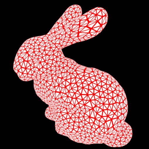
Until now, we’ve been defining \(W\) on barycentric coordinates space. This method works fine for fairly regular triangles (all sides with equal size). However, streched triangles will show edges with varying width. See the edges on the bunny ears for example:
We might improve our results a little bit by trying to normalize things. Lets think about the actual sizes of our triangle: the side vectors \(a\), \(b\), and \(c\), and in particular, the heights \(H_a\), \(H_b\), and \(H_c\):

In barycentric coordinates terms, all these heights measure \(1\) (that is why things get weird in streched triangles). However, we can bring our distances back to the space where our vertices live in. This can be done by scaling each \(\lambda_i\) to its respective height \(H_i\). Remember that each vertex is associated to an \(\lambda_i\): $$A \rightarrow \lambda_1 \quad B \rightarrow \lambda_2 \quad C \rightarrow \lambda_0$$
So, the distance \(D_a\) to edge \(AB\) is \(H_c * \lambda_0\), and the other two are $$D_b = H_a * \lambda_2$$ $$D_c = H_b * \lambda_1$$ where \(D_b\) is the distance to edge \(BC\), and \(D_c\) is the distance to edge \(CA\). The heights can be computed using simple vector projection: $$H_a = || \frac{a\cdot b}{b \cdot b} b - a||$$ $$H_b = || \frac{b\cdot c}{c \cdot c} c - b||$$ $$H_c = || \frac{c\cdot a}{a \cdot a} a - c||$$
Now, our fragment test becomes: $$\min D_{a,b,c} \leq W$$ Shader-Based Wireframe Drawing